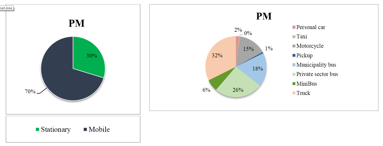
Iran’s big cities air pollution is one of the major challenges to authorities in view of public health. Tehran City, with about 10 Million resident, has been facing more and more air quality problems over the last decades. The criteria pollutants in Tehran are PM2.5, PM10. Particulates and especially ultrafine particles have been identified as the most toxic component of the polluting mixture. Considering diesel engine operation concepts, these types of engines are one of the main source emission of ultrafine particles in urban areas. So controlling particulates emitted from these sources, is one of the first steps to improve air quality. Diesel Particulate Filters (DPFs) are well-known and effective way to reduce particles number and mass. Lately, the Iranian government decided to legislate DPF installation for High Duty diesel Vehicles (HDV). Both, national and international engine industries and experts are now challenged to comply according to the new upcoming standards.
DPF Installation on BRTs’ Feasibility Study Project
ASA is the first private company have been participated at the first DPF project of Iran. In January 2014, the City Council of Tehran decided to order the retrofit of the public bus fleet of the capital. So DPFs’ feasibility study project is organized by Tehran Air Quality Control Company (AQCC). The project consists of two phases. Phase one is particle filter tests on the engine lab was provided in Tabriz for approval of DPFs in Iran. During this phase different types of DPFs from various companies were tested according to VTF1[1] test procedure, by FCE[2] under supervision of VERT association.
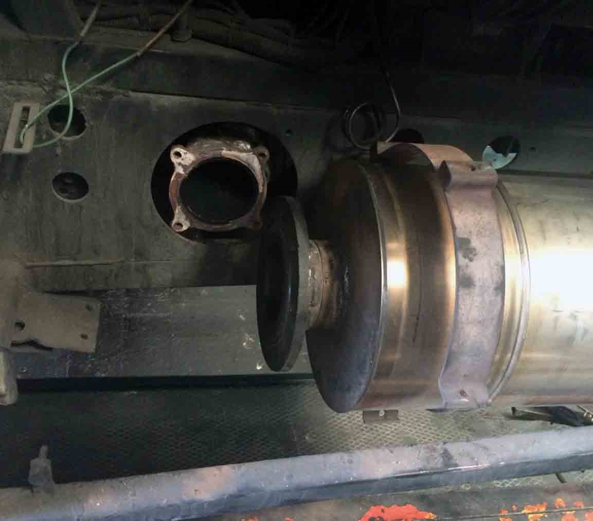
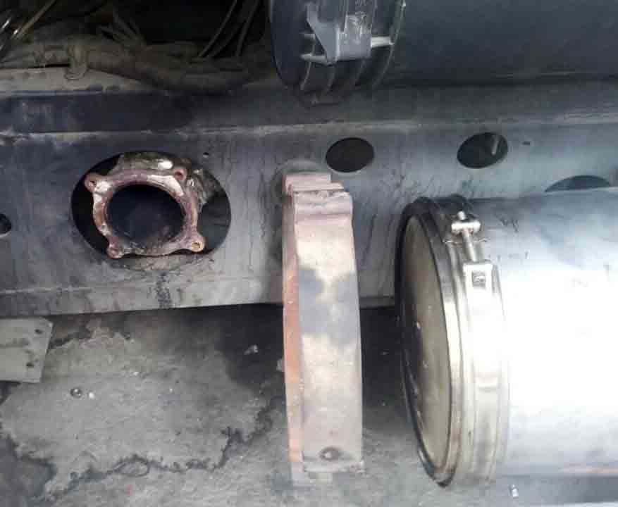
After analyzing phase one results, approved DPFs were sent to Tehran, for fieldwork tests. 18 BRT[3] from different lines with various working paths, were selected and equipped with data logger by ASA[4]. Selected buses operational function were evaluated and analyzed for DPF installation feasibility. By the time ASA installed 8 DPFs on these samples and their data have been collected and analyzed from installation date. ASA Data Analyzer Software (ADAS) have been created and used for this purpose. Analyzed data were published as monthly reports, and were sent to the other beneficiary companies like AQCC, VERT and foreign DPF producer companies. Besides having project related experts, good connection with DPF producer companies make ASA unique at DPF related projects.
ASA’s main tasks at project “feasibility study of DPF installation” second phase:
- Data logger installation
- Analyzing buses operation functional parameters
- DPF installation
- DPF operation monitoring
- Data base creation
- Collecting analyzed data of the project as regular monthly reports
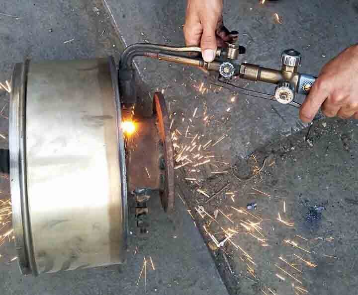
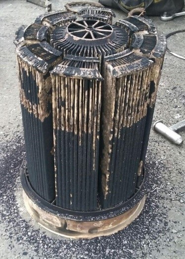
- DPF cleaning and maintenance issue
[1] . VERT filtration test
[2] . Fuel ,Combustion and Emissions group
[3] . Bus rapid transient
[4] . Azmoon Sanat Arvin
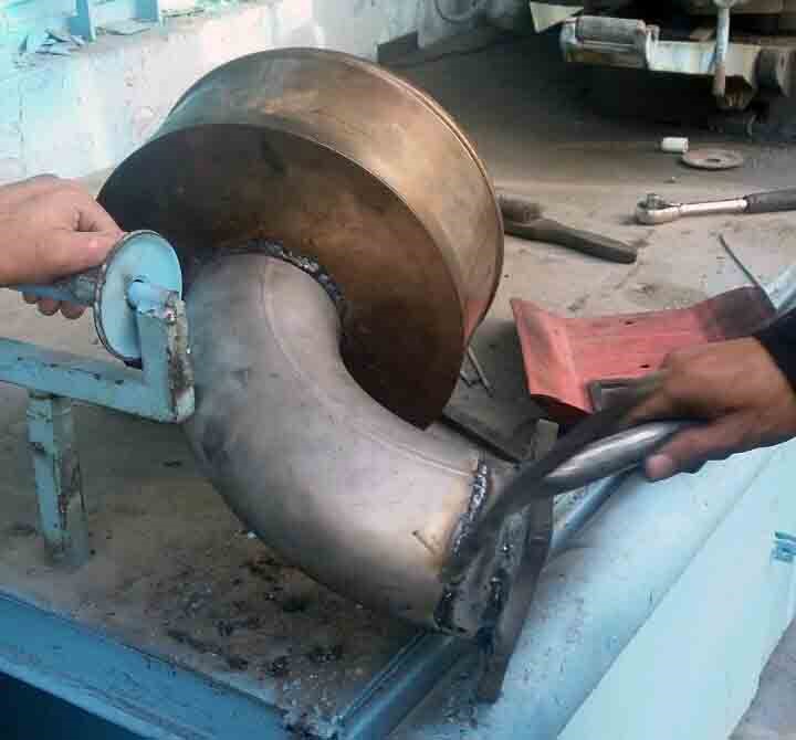
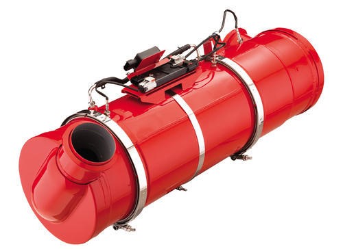
DPF Installation
Monthly reports
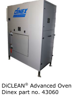
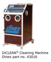
DPF Cleaning and Maintenance
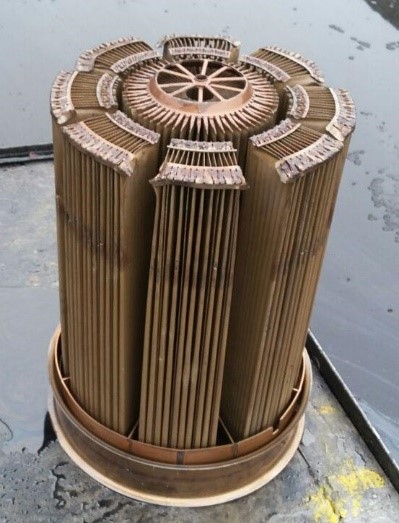
Soot particle emitted from a diesel engine can be efficiently removed from the exhaust gases. The heterogeneous combustion processes in Diesel engines deliver the highest concentrations. Despite intense engineering efforts, the emissions of the numbers of nanoparticles from new diesel engines are not diminished. In recent years various types and configuration has developed so now DPF is well-known for reduction of both mass and numbers of particles and known as a best available technology (BAT) for solving airborne particulates issue.
What is DPF TECHNOLOGY?
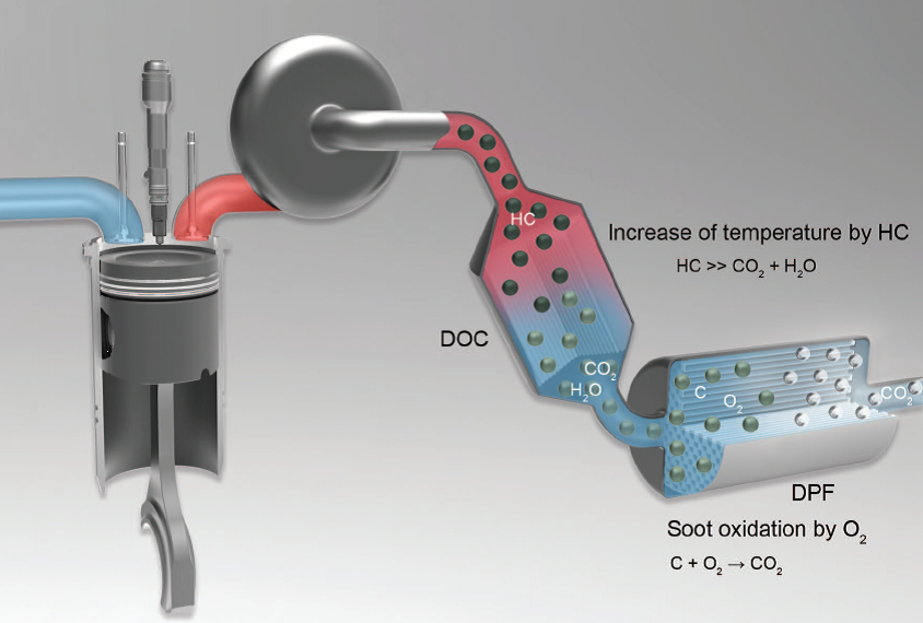
As the name implies, diesel particulate filters remove particulate matter in diesel exhaust by filtering exhaust from the engine. They can be installed on vehicles or stationary diesel engines. Since a filter can fill up over time, engineers that design filter systems must provide a means of burning off or removing accumulated particulate matter. A convenient means of disposing of accumulated particulate matter is to burn or oxidize it on the filter when exhaust temperatures are adequate. By burning off trapped material, the filter is cleaned or "regenerated". Filters that regenerate in this fashion cannot be used in all situations.
Filter Material: A number of filter materials have been used in diesel particulate filters including: ceramic and silicon carbide materials, fiber wound cartridges, knitted silica fiber coils, ceramic foam, wire mesh, sintered metal structures, and temperature resistant paper in the case of disposable filters. Collection efficiencies of these filters range from 50 to over 90 percent. Filter materials capture particulate matter by interception, impaction and diffusion. Filter efficiency has rarely been a problem with the filter materials listed above, but work has continued to: 1) optimize filter efficiency and minimize back pressure, 2) improve the radial flow of oxidation in the filter during regeneration, and 3) improve the mechanical strength of filter designs.
DPF Types
Diesel particulate filter (DPF) systems are designed by combining different filter materials with selected regeneration methods. A classification of diesel filter systems based on the principle of regeneration is shown in below chart. A diesel filter system must provide reliable means of regeneration, preferably a fully automatic regeneration occurring without an intervention (or even knowledge) of the vehicle operator. An alternative would be to use disposable filters—a solution that has been accepted only in certain very specialized niche market applications.
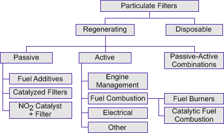
Figure 1. Classification of Filter Systems by Regeneration Method
The majority of regenerating diesel filter systems utilize thermal regeneration, during which the particulates are oxidized to produce gaseous products. The temperature of the diesel exhaust gas is, however, too low to sustain auto-regeneration of the filter. That problem may be solved by either (1) decreasing the required soot oxidation temperature to a level which is reached during regular engine operation or (2) increasing the temperature in the filter to the point where the trapped soot starts oxidizing. The first approach is used in passive filter systems, the second in active filter systems.
Passive Systems
This is based on chemical reactions that take place in the engine’s exhaust aftertreatment system. First of all, nitrogen dioxide (NO2) is produced in the oxidation catalyst from the nitrogen monoxide (NO) in the exhaust gas. In the diesel particulate filter, the process is reversed and the soot deposited in the diesel particulate filter is continuously burned off. Hence the name “Continuous Regeneration Trap” (CRT), i.e. a continuously regenerating filter. This effect is also referred to as passive regeneration. In contrast to active regeneration, the reaction requires no additional energy.
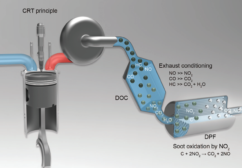
In passive systems the soot oxidation temperature is lowered to a level allowing for auto-regeneration during regular vehicle operation—a task commonly achieved by introducing an oxidation catalyst to the system. The catalyst can promote oxidation of carbon through two mechanisms:
- Oxygen mechanism—catalytic oxidation of carbon by oxygen, or
- Nitrogen dioxide mechanism—catalytic oxidation of NO to NO2, followed by the oxidation of carbon by nitrogen dioxide.
Through different placement of the catalyst and different system configuration one can utilize either one of these mechanisms or their combination. Three major approaches have been used: (a) adding a catalyst precursor to the fuel as an additive, (b) placing the catalyst directly on the filter media surface, or (c) using an NO2 generating catalyst upstream of the filter.
Active Systems
The second approach is to actively trigger regeneration by raising the temperature of soot trapped in the filter through the use of an outside energy source.
If an engine runs under very low load, the exhaust gas temperature can drop to a point where continuous regeneration can no longer be completely guaranteed. In order to prevent the diesel particulate filter being overloaded when operating under such conditions for a long time, additional thermal energy must be introduced for a short time into the exhaust gas. That can be done, for instance, by injecting fuel into the combustion chamber in one or more post injection sequences or injecting fuel directly into the exhaust system. This fuel is then completely burned in the engine’s oxidation catalytic converter. In this process, it releases enough heat to raise the exhaust temperature in the particulate filter to over 550 degrees Celsius. The use of a burner is also possible. As a result, the deposited diesel soot oxidizes with the surplus oxygen present in the exhaust gas. Active regeneration of the particulate filter is used primarily in cars and commercial vehicles with high specific soot emission levels.
There are two obvious energy sources that are available on-vehicle: diesel fuel and electricity. The energy from fuel combustion can be used to increase exhaust gas temperature by either (1) in-cylinder engine management methods, such as late cycle injection of additional fuel quantities, or (2) injection and combustion of fuel in the exhaust gas. If exhaust gas combustion is used, fuel can be burned in a fuel burner or else oxidized over an oxidation catalyst, in a catalytic combustion process.
Electric heating can be used in a number of configurations, such as—for example—placing an electric heater upstream of the filter substrate, incorporating heaters into the filter media, or using electrically conductive media (such as metal fleece) which can act as both the filter and the heater. A stream of heated air can be also utilized to trigger regeneration, rather than heated exhaust gas.
The third category of systems in Figure 1 utilize the combination of passive and active regeneration, where a catalyst-based filter is also equipped with some kind of an active regeneration system. Some authors refer to this approach as the passive-active system, others call it the quasi-active filter, still others simply consider it a form of the active regeneration system. The use of catalyst allows to perform regeneration at a lower temperature and/or to shorten the regeneration time period, compared to non-catalytic active systems. In either case, the fuel economy penalty associated with active regeneration can be minimized (at an added cost of the catalyst). Regeneration at a lower temperature also results in lowering thermal stress and increasing lifespan of the filter media.
Passive-active combinations, depending on the type and loading of the catalyst, may be able to sustain fully passive operation during periods of increased exhaust temperature. For instance, a catalyzed filter in a passenger car may regenerate passively during fast highway driving, but will depend on active regeneration—which could be triggered by an engine management strategy—during low speed city driving.
Regeneration
Many techniques can be used to regenerate a diesel particulate filter. Some of these techniques are used together in the same filter system to achieve efficient regeneration. Both on- and off-board regeneration systems exist. The major regeneration techniques are listed below.
- Catalyst-based regeneration using a catalyst applied to the surfaces of the filter. A base metal or precious metal coating applied to the surface of the filter reduces the ignition temperature necessary to oxidize accumulated particulate matter.
- Catalyst-based regeneration using an upstream oxidation catalyst. In this technique, an oxidation catalyst is placed upstream of the filter to facilitate oxidation of nitric oxide (NO) to nitrogen dioxide (NO2). The nitrogen dioxide reacts with the collected particulate, substantially reducing the temperature required to regenerate the filter.
- Fuel-borne catalysts. Fuel-borne catalysts reduce the temperature required for ignition of trapped particulate matter. These can be used in conjunction with both passive and active filter systems.
- Air-intake throttling. Throttling the air intake to one or more of the engine cylinders can increase the exhaust temperature and facilitate filter regeneration.
- Post top-dead-center (TDC) fuel injection. Injecting small amounts of fuel in the cylinders of a diesel engine after pistons have reached TDC introduces a small amount of unburned fuel in the engine's exhaust gases. Fuel can also be injected into the exhaust pipe. This unburned fuel can then be oxidized in the particulate filter to combust accumulated particulate matter.
- On-board fuel burners or electrical heaters. Fuel burners or electrical heaters upstream of the filter can provide sufficient exhaust temperatures to ignite the accumulated particulate matter and regenerate the filter.
- Off-board electrical heaters. Off-board regeneration stations combust trapped particulate matter by blowing hot air through the filter system.
Another types for classification of DPFs:
Wall-flow diesel particulate filter
In the case of a wall-flow diesel particulate filter, the entire exhaust flow is passed through the fine porous ceramic walls of the filter element. This makes very high particle filtration rates of over 90 percent possible. However, filter regeneration must be possible in a wide range of engine applications, to prevent clogging. The resulting high exhaust backpressure would lead to higher fuel consumption and, in the worst case, to filter and engine damage. Consequently, including the engine’s thermal management measures is of particular importance in the development of the system. Wall-flow particulate filter systems can be combined both with passive and active regeneration.
Partial-flow diesel particulate filter
A partial-flow diesel particulate filter, strictly speaking, is a particle separator. The separation effect is based on a sharp deflection of the exhaust gas flow that results in some of the particles to be separated. Compared with a wall-flow diesel particulate filter, it produces similar and in some cases higher exhaust backpressures. A partial-flow diesel particulate filter cannot clog up. However, the filtration rate with an exhaust pressure comparable to that of a wall-flow diesel particulate filter is only 30 to 40 percent.
How it works
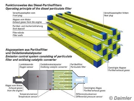
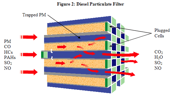
Figure 2 provides a diagram of a typical high-efficiency, wall-flow filter system. High-efficiency, wall-flow filters have demonstrated the ability to reduce diesel particulate emissions by more than 90 percent in retrofit applications.
In the figure, particulate-laden exhaust enters the filter from the left. Because the cells of the filter are capped at the downstream end, exhaust cannot exit the cell directly. Instead, exhaust gas passes through the porous walls of the filter cells. In the process, particulate matter is deposited on the upstream side of the cell wall. Cleaned exhaust gas exits the filter to the right.
A DPF needs to grant two major functions: The first is to filter as many particulates as possible out of the exhaust gas. The second is to support different regeneration strategies of a DPF system, in order to remove the soot from the filter. Filtration and regeneration are therefore the most crucial elements of a particulate filter. The filter needs to stand high temperatures, especially when high soot loads are combined with active regeneration. Diesel particulates evolving from engine combustion are carcinogenic to humans. Being just some nanometers big, they could be inhaled easily. The target of a high tech filter material is to filter even the smallest particles, without increasing the back pressure significantly. Our experience from different applications all over the world shows that Silicon Carbide (SiC) material masters all these requirements on a high professional level.
Why DPF
Diesel particulates deriving from engine combustion are definitely carcinogenic. In the past this matter of fact was often disregarded. In June 2012 the World Health Organization (WHO) confirmed the dangerousness of diesel particulates and consequently classified them as a “group 1: definitely carcinogenic to human beings” harmful substance. Hence, diesel particulates are ranked on the same level as e.g. asbestos.
Diesel particulates are dangerous to the health of humans. Therefore PM emissions are an important value for engines in new vehicles and for the emissions of older vehicles as well. In order to protect people, retrofit programs were launched targeting the upgrade of older engines to latest emission technology.
Switzerland has been the hotbed of all PM emission reduction movement. Already in the 80s they draw a line between PM emissions and respiratory diseases of workers. The Swiss compensation insurance (SUVA) mandated a study finding the relation between costs of retrofit and medical expenses for recreation and integration of sick people. The result was striking and since then, especially construction equipment has to have a DPF system fitted. Consequently Switzerland was the first country making up their mind about a DPF standard. The target was to establish a technical procedure of testing a DPF retrofit system if it complies with the demands of the industry and the health aspects.
Today the VERT standard (verified emission reduction technologies) is one of the hardest and well respected international standards. Many national rules have their roots in the approval procedure of VERT.
Why are particle filters needed?
The problem is a sharp Intensification of the health risks in all urban agglomerations, due to rapid increase in motorized traffic during the past 50 years. Fine particles in the alveoli intruding range are "Toxic substance Number 1". These ultrafine solid particles in the size range < 500 nm are exclusively anthropogenic, resulting from technical combustion, I.e. from stationary combustion e.g. building heating, but above all from the combustion engines. All engines produce these fine particles, both as soot and also ultrafine metal oxides from abrasion and lube oil additives. However, the heterogeneous combustion processes in Diesel engines deliver the highest concentrations. Despite intense engineering efforts. the emissions of the number of nanoparticles from new IC-engines are not diminished. Indeed, deterioration is observed, due to emission of smaller particles than from the older models. The famous 6-Cities US Study (Dockery 1993) first showed the strong impact of the ultrafine particle content on the residents' mortality, Including the carcinogenic and cardiovascular consequences. The WHO has quantified the total effect for several countries. The statistics for Switzerland reveal the magnitude of this risk, which is now at least 6-fold higher than the risk of traffic accidents. This is representative for all other industrialized countries.


The two lower Figures illustrate that mainly the very fine particles Intrude Into the lung and from the lung are transported to other body organs. This penetration contrasts with the response to particles > 1 µ. Those larger particles are efficiently Intercepted and expelled, thanks to the respiratory cleansing mechanism, which has naturally evolved. Clearly the particle size Is a major factor and, of course, the particle solubility. Hence, the modern approach focuses on the solid particles in the alveoli-intruding size range. The WHO classifies these particle emissions, since 1988 as carcinogenic. This fact has prompted environmental legislation, in many countries, stipulating the minimizing of such emissions using the best available technology. Because there is no safe threshold for carcinogenic substances. That requirement defines the engineering task: determine which exhaust-gas after-treatment Is the "best available technology" and decide how widely it should be employed to curtail the combustion engine emissions. This task comprises both new engines and also the presently deployed engines. The extension to existing engines, I.e. retrofitting, bounds the technology choice and is very demanding on the application technique.
Historically, legislation is confined to rules for new vehicles. The emission legislation ameliorates the recognized health risks through progressively more stringent emission limits. This tightening exhaust-gas legislation is a big challenge to the engine manufacturers that has required expensive engineering. Figure 3 Illustrates the advancement of exhaust-gas legislation for utility road vehicles and for off-road vehicles (construction machines, tractors, etc.) in Europe.

These particle limiting values are defined as the total particle mass (PM, g/kWh). This metric Is inadequate for EUR04/EUR05 because their PM is approaching the detection limits. The question also arises, whether the PM metric represents the significance of particle size described above. Ultrafine particles in the 100 nm range have a very small mass in the mix of larger and smaller particles. The modern engines indeed attain the legislated limits but continue to emit high concentrations of extremely toxic ultrafine particles, which are preventable. Nevertheless note that this modern technology also has disadvantages. The platinum coated oxidation catalytic converters, in PM·Cat, can substantially increase the undesirable No2. And the SCR technology can cause ammoniac slip and release other toxins, which are not yet sufficiently Investigated. These are secondary emissions, which must be prevented (testing mandatory in Switzerland and in USA) when introducing new technologies. Numerous Investigations In past decades have researched methods to curtail the particle emissions from Diesel engines. The following methods were investigated:
- Oxidation catalytic converters
- Fuel additives
- Sulfur-free fuel
- Bio fuels
- Water I Diesel emulsions
- Improved lubrication oils
- Optimizing the combustion, the fuel injection and the supercharging
Many methods can diminish the mass PM, comprising the solids and condensates. The ultrafine particles are at the most decreased by one order of magnitude. It is Insufficient compared to good particle filters that can diminish ultrafine particles by 3 to 5 orders of magnitude. The efficiency of this filter is higher for smaller particle sizes. That Is a desirable feature in view of their toxicity. This effect is physically plausible because of the diffusion behavior of ultrafine particles. The particle content of the exhaust-gas is thus diminished below the particle content of the environment. Besides the soot particles, all heavy metal particles from abrasion and lube oil are intercepted, too. Also filtered are mineral particles and fiber fragments, e.g. from the mufflers. This outstanding attribute of modern particle filters Is sustained over long time periods. There are no Indications of deterioration due to aging. All particle filters not only curtail the solid particles. They also curtail the concentration of the polycyclic aromatic hydrocarbons, which adhere to the particles. Many filters, when catalytic coated, also diminish CO and HC. Some particle filters Increase the No2 content of the exhaust-gas. Selecting the appropriate finer regeneration technology can prevent the undesirable NO2 effect.
Costs and Benefit/Cost ratio
Figure 4 shows the specific Installation costs in CHF pro kW, It is based on present market prices, mainly influenced by deployment on construction site machines.

High costs persist. The slope of the curve Indicates the unfavorable circumstances for smaller machines, which suffer very high specific costs. If the cost Impact were formulated as cost/kg soot disposed, then the curve would be almost horizontal. The data for filter fitted ex-factory, both trucks and car manufacturing, shows the possible economies. The retrofitting costs should not be underestimated. Usually, much customized retrofitting is necessary, which is expensive. Further cost reductions will result, when larger unit volumes rationalize retrofit kits that lower fitting expenses. Nevertheless, the heterogeneity of construction machines would keep costs high. More promising are lower costs for utility vehicles. These benefit from more uniformity in vehicle types, deployment range and the placement situation. These high costs are macro-economically justified when there are comparable financial benefits In saving medical expenditure. The following table Intend to quantify the cost I benefit ratio, for various deployment situations, I.e. the cost to prevent 1 kg of emitted soot comparing the use of high efficiency wall flow filters for HCV to partial flow filters for LDV as well as for off-road/construction machines.

Clearly, the Cost/Benefit for retrofitting high efficiency wall flow filters at HDV at apparently high costs is much more cost efficient than the use of partial flow filters as they are proposed for retrofitting LDV and the Cost/Benefit for off-road and construction equipment where filter retrofit cost is again higher Is very affordable for large and for small engines ~use of the high emissions from these small engines. Moreover, the deployment of partial flow (open) filters on cars has a very poor cost/benefit ratio, i.e. such products should be definitely avoided. A useful benchmark, for evaluating these cost/benefit ratios, Is the WHO value for the so-called external health costs proposing 280 Euro per kg soot.